HC 12 Uart Transciever Part-3 Improved code – Sharing Code
|
1 2 3 4 5 6 7 8 9 10 11 12 13 14 15 16 17 18 19 20 21 22 23 24 25 26 27 28 29 30 31 32 33 34 35 36 37 38 39 40 41 42 43 44 45 46 47 48 49 50 51 52 53 54 55 56 57 58 59 60 61 62 63 64 65 66 67 68 69 70 71 72 73 74 75 76 77 78 79 80 81 82 83 84 85 86 87 88 89 90 91 92 93 94 95 96 97 98 99 100 101 102 103 104 105 106 107 108 109 110 111 112 113 114 115 116 117 118 119 120 121 122 123 124 125 126 127 128 129 130 131 132 133 134 135 136 137 138 139 140 141 142 143 144 145 146 147 148 149 150 151 152 153 154 155 156 157 158 159 160 161 162 163 164 165 166 167 168 169 170 171 172 173 174 175 176 177 178 179 180 181 182 183 184 185 186 187 188 189 190 191 192 193 194 195 196 197 198 199 200 201 202 203 204 205 206 207 208 209 210 211 212 213 214 215 216 217 218 219 220 221 222 223 224 225 226 227 228 229 230 231 232 233 234 235 236 237 238 239 240 241 242 243 |
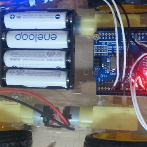
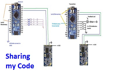
/*By Roee Bloch - Version 4 * This includes: Latch Mode, Momentary Mode (selected by A5 input), and also feedback to Transmitter that the Receiver got transmission OK - by LED on Transmitter * Controls 4 logic output at 2 modes: Latch (each press change output ON/OFF), Momentary (output on just when button is pressed) *HC-12 Moule Transciever Same code is for Transmitter and Receiver, setup through A4 Input *Tested on Arduino Nano * This SW is for Transmitter & Receiver, the choise is done by reading A4 & A5 inputs (analog inputs) * A4=1=> TX, A4=0=>RX * A5=1=>LATCH (Default mode), A5=0=>Momentary the stting now is via variable latch_logic if 1=> latch if 0=> momentary * * NANO connections to HC-12 As follows: * ARDUINO NANO HC-12-MODULE * _________________________________________________________________________ * 5V -> 1N4148 Anode, 1N4148 catode -> HC-12/Pin-1 (VCC) * GND -------> GND * D11 -------> RXD * D10 -------> TXD * * NANO (TX MODULE) NANO (RX MODULE) * ______________________ ________________________________ * D2 --> SW --> GND (SW1) A4 --> GND * D3 --> SW --> GND (SW2) D2 --> OUTPUT 1 * D4 --> SW --> GND (SW3) D3 --> OUTPUT 2 * D5 --> SW --> GND (SW4) D4 --> OUTPUT 3 * D5 --> OUTPUT 4 * * FEEDBACK back will light Led on Trnasmitter for 100mS * See connection Diagram here: * https://goo.gl/photos/qog8gWPKpSDPgZen7 * */ #define P1 2 #define P2 3 #define P3 4 #define P4 5 #define F1 6 // feedback back to transmitter //#define latch_logic 1 // if 1 then latch if 0 momentary #include <SoftwareSerial.h> SoftwareSerial mySerial(10, 11); // RX, TX char latch; // , if latch=1 then Latch int read_A4, read_A5, i, read_P1, read_P2, read_P3, read_P4; int TX_CODE, RX_READ, mode, TX_CODE_OLD; //if mode= 1 then TX int RP1, RP2, RP3, RP4; volatile byte SW1 = 0, SW2 = 0, SW3 = 0, SW4 = 0; boolean S1, S2, S3, S4; byte TEST; char TXTOSEND,feedback; int FLAG=1,latch_logic; void setup() { Serial.begin(9600); mySerial.begin(9600); Serial.println("Hello HC-12 TX and RX SW, A4-Low=TX A4-HIGH=RX A5-LOW=Momemtary A5-HIGH=LATCH"); // mySerial.println("Hello HC-12 TX and RX SW, A4-Low=TX A4-HIGH=RX A5-LOW=Momemtary A5-HIGH=LATCH"); // This is for internal pull ups resistors on A4 and A5 Inputs delay(500); pinMode(A4, INPUT_PULLUP); pinMode(A5, INPUT_PULLUP); read_A4 = analogRead(A4); read_A5 = analogRead(A5); if ((read_A4) > 500) { mode = 1; Serial.println("TX Mode"); } else { mode = 0; Serial.println("RX Mode"); } if ((read_A5) > 500) { latch = 1; latch_logic=latch; Serial.println("LATCH Mode"); } else { latch = 0; latch_logic=latch; Serial.println("Momentary Mode"); } if (mode == 1) // TX { pinMode(P1, INPUT); // set pin to input digitalWrite(P1, HIGH); // turn on pullup resistors pinMode(P2, INPUT); // set pin to input digitalWrite(P2, HIGH); // turn on pullup resistors pinMode(P3, INPUT); // set pin to input digitalWrite(P3, HIGH); // turn on pullup resistors pinMode(P4, INPUT); // set pin to input digitalWrite(P4, HIGH); // turn on pullup resistors pinMode(F1, OUTPUT); // set pin to input digitalWrite(F1, LOW); } else { pinMode(P1, OUTPUT); // set pin to input digitalWrite(P1, LOW); // turn on pullup resistors pinMode(P2, OUTPUT); // set pin to input digitalWrite(P2, LOW); // turn on pullup resistors pinMode(P3, OUTPUT); // set pin to input digitalWrite(P3, LOW); // turn on pullup resistors pinMode(P4, OUTPUT); // set pin to input digitalWrite(P4, LOW); // turn on pullup resistors } } void loop() { if (mode == 1) //TX Mode { TX_MODE(); } else { RX_MODE(); } } void TX_MODE() { while (1) { { read_P1 = digitalRead(P1); read_P2 = digitalRead(P2); read_P3 = digitalRead(P3); read_P4 = digitalRead(P4); TX_CODE = 64 + (read_P1 * 1) + (read_P2 * 2) + (read_P3 * 4) + (read_P4 * 8); // converting TX to one char TXTOSEND = TX_CODE; // conver to char for sending OK if (FLAG==0) // skip first time on FLAG=1 { if (latch==1) { if ((TX_CODE != TX_CODE_OLD)&&(latch_logic==1)) // transmit only on change { Serial.print(TX_CODE, BIN); mySerial.print(TXTOSEND); } delay(100); TX_CODE_OLD = TX_CODE; } else { Serial.print(TX_CODE, BIN); mySerial.print(TXTOSEND); delay(100); } } else FLAG=0; } feedback=mySerial.read(); if (feedback=='R') { Serial.println("Data_Sent_OK"); // feedback to serial port digitalWrite(F1, HIGH); // Ligjt Led Back on Transmitter delay(80); digitalWrite(F1, LOW); } } } void RX_MODE() { while (1) { if (mySerial.available()) { // read the incoming byte: RX_READ = mySerial.read(); TEST = RX_READ; RP1 = (TEST) & (1); RP2 = (TEST) & (2); RP3 = (TEST) & (4); RP4 = (TEST) & (8); mySerial.flush(); // When button is pressed (logic 0) toggling the apropriate LED Latch mode only if ((latch==1)&&(latch_logic==1)) { if (RP1 == 0) SW1 = ~(SW1); if (RP2 == 0) SW2 = ~(SW2); if (RP3 == 0) SW3 = ~(SW3); if (RP4 == 0) SW4 = ~(SW4); mySerial.print("R"); // This is feedback back to transmitter } else // Momentary mode ON only when button is pressed continously { if (RP1 == 0) { SW1 = 1; mySerial.print("R"); // This is feedback back to transmitter } else SW1=0; if (RP2 == 0) { SW2 = 1; mySerial.print("R"); // This is feedback back to transmitter } else SW2=0; if (RP3 == 0) { SW3 = 1; mySerial.print("R"); // This is feedback back to transmitter } else SW3=0; if (RP4 == 0) { SW4 = 1; mySerial.print("R"); // This is feedback back to transmitter } else SW4=0; } //convert to bit for Digital-Out from Arduino S1= SW1 & 1; S2= SW2 & 1; S3= SW3 & 1; S4= SW4 & 1; digitalWrite(P1, S1); digitalWrite(P2, S2); digitalWrite(P3, S3); digitalWrite(P4, S4); delay(100); Serial.print("S1="); Serial.print(SW1); Serial.print(" S2="); Serial.print(SW2); Serial.print(" S3="); Serial.print(SW3); Serial.print(" S4="); Serial.println(SW4); } } } |
You can Buy it from Ebay here: HC-12 Module On Ebay Link
You Can Buy it from Amazon here: HC-12 Module From Amazon
You Can Buy it from Ali-express here:
 AliExpress.com Product – 1pcs 433Mhz HC-12 SI4463 Wireless Serial Port Module 1000m Replace Bluetooth NEW
Link to USB to UART for Configuring the Module on Ebay: USB FT232 Dual Voltage configuration
Connection Diagram is here: Connection Diagram
Link to Manual: Manual PDF