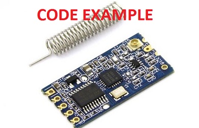
code example
// Just stamping every 10 seconds after 's' is pressed
/*Arduino Nano connection to Module:
 * Connect Power from Arduino Nano From 5V to Module VCC (use Diode 1N4148 to lower the voltage and protect Module)
 * Connect GND from Arduino Nano to Module GND
 * Connect Arduino Nano D10 to Module TXD will use MySerial for data-in to Module
 * Connect Arduino Nano D11 to Module RXD again we will use the MySerial command (Software Serial)
 * Connect in Module Between VCC to GND 100uF capacitor close as possible to Module Power Pins - This will improve performance of the Module
 */
#include "SoftwareSerial.h";
SoftwareSerial mySerial(10, 11); // RX, TX
int i=0;
char s;
void setup() {
  Serial.begin(9600);
  mySerial.begin(9600);
  Serial.println("Hello starting in 5 seconds");
  mySerial.println("Hello starting in 5 seconds");
  delay(5000);
  Serial.println("Waiting for Pressing s ");
  mySerial.println("Waiting for Pressing s ");
}

void loop() {

  while(s!='s')
  {
  if (mySerial.available())
    {
       s=mySerial.read();
       if (s=='s')
       {
        Serial.println("Starting now ......");
        mySerial.println("Starting now ......");
       }
    }
  }

   Serial.print("Passed: ");
   Serial.print(i);
   Serial.println(" Seconds ..");
   mySerial.print("Passed: ");
   mySerial.print(i);
   mySerial.println(" Seconds ..");
   i=i+1;
   delay(1000);
}
First in order to Program Connect Module “SET” Pin to GND and then power on Module
Make sure you are in 9600 BAUD rate and ‘Carriage Return’
Use These Commands:
‘AT+RP’ – read power
‘AT+RC’ read current channel
check by writing ‘AT’ make sure you get ‘OK’ if you got this so you are OK!
‘AT+C001’ – This Choose Channel1
‘AT+P1’ – Lowest Power out (0.8mW)
Read Power: ‘AT+RC’ you will get ‘RP:-01dBm’
‘AT+P8’ – Highset power 100mW (reading you will get ‘OK+RP:+20dBm’)
‘AT+B19200’ – Set Baud rate to 19200
‘AT+RB’ – read out Baud rate, You will get ‘OK+B19200’
‘AT+V’ – read SW Version on Mdule, My Module gives back ‘HC-12_V2.3’
‘AT+DEFAULT’ get everything to Default Mode
‘AT+Udps’ – This Set UART as followos: Set data bits (d), parity (p), and stop bits (s) for serial port communication. For parity, N means none, O means odd check, and E means even check. For stop bits, 1 means one stop bit, 2 means two stop bits, and 3 means 1.5 stop bits
You can Buy it from Ebay here: HC-12 Module On Ebay Link
You Can Buy it from Amazon here: HC-12 Module From Amazon
You Can Buy it from Ali-express here:
 AliExpress.com Product – 1pcs 433Mhz HC-12 SI4463 Wireless Serial Port Module 1000m Replace Bluetooth NEW
Link to USB to UART for Configuring the Module on Ebay: USB FT232 Dual Voltage configuration
Link to Manual: Manual PDF
